DESIGNING PHYSICAL INTERFACES:
interacting with our world
May 31 - June 9, 2004
instructors: eric forman & cynthia lawson
LECTURE 5: SERIAL COMMUNICATION
INTRODUCTION
- Serial = most common method
- Shared language (“protocol”)
- Computer <--> BX-24 <--> Serial Device
In order for two devices to communicate with one another, they need to share a form of communication and a common language. The most widely form of communication is serial communication. The types of devices that can communicate serially include computers, a diverse number of serial chips (e.g. serial LCD) and peripherals (e.g. printers), and microcontrollers, including the BX-24.
For the purposes of this class, we will be focusing on one distinct communication: between the microcontroller and the computer. As we will study ahead, it is important to understand both how the computer “talks” to the BX, as well as the BX to the computer.
DATA TRANSMISSION
- BX-24 <--> Computer (software)
- Protocol: data rate
- TX, RX, GND, ATN
- BasicX software <--> BX-24
Successful communication relies on devices using the same protocol. For two devices to successfully “talk” to each other, they both need to expect pulses in a certain voiltage range, transmitted at an exact speed, in a certain order. Data rate is the primary aspect of a communication protocol. This rate defines the amount of information per second that’s being transmitted (e.g. 9600 bits per second.) The speed of data transmission is also called “baud,” and is usually expressed in kbps, kilobits per second. For example a 56.6k modem communicates with a computer at 56,600 bits/sec, or 7,075 bytes/sec.
Other components of a serial communication protocol are number of databits, stop bit, and parity - but these are almost always set the same so you shouldn’t have to worry about them. (8 databits, 1 stop bit, no parity if you’re interested.)
Software plays a key role in serial communication, since, if one of the devices is the computer, it is through software that we most commonly establish the communication. In our example, the software will be Macromedia Director. NOTE: the BX is programmed via a serial cable, through which the program written in the development software is downloaded to the BX chip. When the BX sends debug statements, it is sending serial data over the same cable back to the computer. Therefore, BX software can also be considered as the software interfacing serially with the chip.
MAKING A SERIAL CABLE
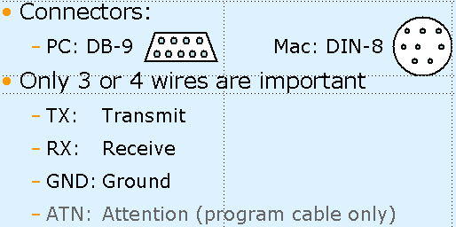
Serial cables can be purchased in most computer stores. There are both Mac and PC cables, since these two computer platforms have different cable connectors that need to be used. For a PC, the cable end or form needed is called DB-9, and the protocol it follows is RS-232. Mac uses the RS-422 protocol and a DIN-8 connector similar to printer or modem cables. We will be modifying these standard cables a bit to get them to work with our microcontroller.
NOTE: If your computer does not have a serial port, but only USB, you can use a USB serial port adaptor in order to communicate with the BX-24.In terms of hardware, the two devices need to be connected via a serial cable which has three key wires: TX, RX, and GND. In addition sometimes a fourth signal wire, ATN, is needed (in this case only for programming). TX stands for Transmit, and it’s the wire that sends the data from device A to device B. RX, or Receive, is the wire for device A to receive data from device B. (Here we will discuss TX and RX from the microcontroller’s point of view.) GND, Ground, is what creates a common voltage reference level between the two device. ATN, Attention, is used as a flag for a device to “announce” it is ready to transmit and/or receive - it is not needed in a regular serial cable.
If you’re using a PC for your output, you can use your programming cable as a serial cable - just leave the ATN pin of the cable unconnected.
Remember that TX and RX are usually labeled locally - that is, a TX pin on device A should connect to the RX pin on device B and vice versa.
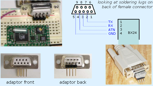
Making a little DB-9 adaptor is the quickest way to make a programming cable. Simply plug it in to one side of a standard PC serial cable.
Solder right-angle headers to the soldering lugs on the back of a female DB-9 connector. You’ll be connecting pins 2-5 of the serial cable to pins 1-4 of the BX. If you don’t have right-angle headers, bending straight headers can work. You can also cut off the end of the serial cable and solder headers directly to the appropriate wires within (you’ll have to do this if you’re making a Mac serial cable).
The whitish blob visible in the photo of a serial cable with adaptor attached is hot glue - this is a great, cheap way to reinforce your soldering joints and is especially useful for high-stress parts like cable connectors.
Note: You can only program the BX with the BasicX software on a PC (although it could be done with some difficulty with a serial-USB adaptor on a Mac running PC emulation software like VirtualPC).
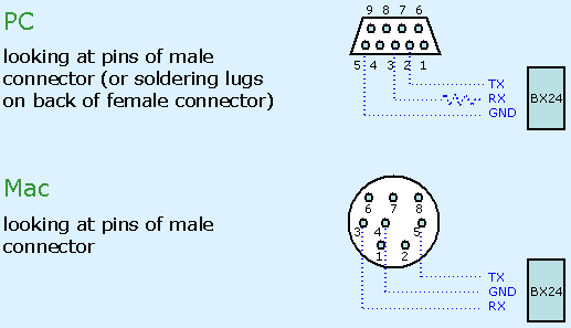
The BX-24 can use any two pins as its serial port. It is easiest to have these pins be right next to each other. It can also use the same pins through which you program it, but it is usually recommended to define different pins for the serial communication keeping the programming serial port free so that you can reprogram without changing wiring.
Macs communicate at 9 volts, while PCs use 12V. 9V is close enough to the 5V the BX expects, but if you are communicating from a PC to the microcontroller, it is important to use a resistor to limit the voltage at the receiving pin of the BX. A 22k resistor is standard but it doesn’t need to be exactly that, over 15k should work (if you are having problems with serial communication you might try reducing the value of the resistor to less than 22k).
Make sure you have the current limiting resistor in place (if using a PC) and that the BX-24 is properly grounded before attaching a serial cable to it.
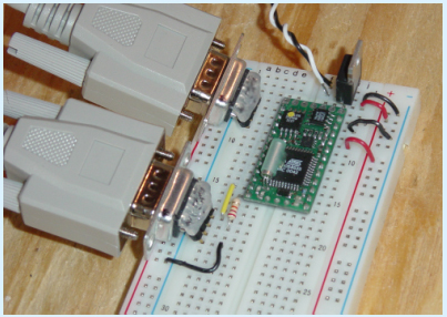
SERIAL CABLE & THE BREADBOARD
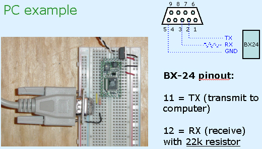
Remember you can use any I/O pins for serial communication, but it makes sense to use digital-only pins since the ADC pins are limited.
The most common technique used in troubleshooting a cable which is malfunctioning is the test of continuity. With a multimeter, you can test if the wire between a pin on both ends of the cable is continuous. Make sure you know what end of the connector you are looking at when comparing it to the pin diagrams.
PROGRAM + SERIAL CABLES
BASICX CODE
- Setting up a serial port in Basic
- Set up buffer variables (byte arrays)
- Define port (COM3)
- Open buffer queues
- Open port (define baudrate)
The BX-24 has two serial ports, called Com1 and Com3 (there is no Com2). Com1 uses pins 1 and 2, and is the port used for programming the chip. Although you can use this port with those same pins for your own purposes, it is much easier to use Com3. Com3 can use any of the I/O pins (5-20); you assign which pin will be used for transmit (TX) and which for receiving (RX) using BX code.
To define the serial port, use the defineCom3 command, specifying the receive, or Serial-In, pin and the transmit, or SerialOut, pin, along with the communication protocol parameters. There are constants defined for different parameter values; you will almost always use bx1000_1000 which means 8 databits, 1 stop bit, no parity.
The BX-24 has a small buffer to store serial data that helps communication to go smoothly. The BX needs 9 bytes of its RAM for serial communication, so the size of the buffer variables above 9 defines the size of the buffers. The buffer variables are declared as arrays of bytes, e.g. declaring an inputBuffer variable as a 13 byte array results in a 4 byte buffer. Because the desktop computer will have no problem with data sent from the BX, there is seldom reason to have a large output buffer.
Before opening the serial port, you open queues so the BX knows to fill in the buffer arrays and take bytes from it one at a time while continuing to fill in the newly open spots. Open queues for both input and output using the buffer multi-byte buffer variables you’ve declared, and defining the size of the queues (usually the same as the size of the buffer variables).
Finally, open the serial port defining which Com port will be used, the data rate, and the buffers. We will use Com3 at 9600 baud.
Defining constants for serial in and out pins is a good habit so you don’t forget which is which in the defineCom3 statement. Naming them serInPin and serOutPin instead of RXpin and TXpin is useful so you don’t forget if the RX is relative to the BX or to the device it’s connecting to (in this case, a desktop computer’s serial port).
To send data out, you send it one byte at a time by putting it in the output queue, using the putQueue command:
call putQueue(buffer, data, numBytes)
buffer: a queue of bytes into which you're going to put the byte to be sent
data: data to be sent; can be any data type (single bytes are the simplest)
numBytes: how many bytes you're putting in the queue. If data is a byte variable, numBytes is 1.Since will be sending the reading of an analog sensor, we have to convert the value of getADC from an integer to a byte. Since getADC returns a value from 0-1023 we can divide it by 4 to translate it to a range from 0-255. Use the \ symbol to divide integers in Basic; the regular / symbol will give an compile error if used with integer variables.
Sending single bytes out of the serial port is easy and rarely goes wrong. If you want to send more than one byte at a time, you will have to set up a system to make sure the devices sort out the data properly. One way is to send a “header byte” before each series of data that the receiving device expects. Another way is to have the receiving device send back a confirmation after each clump of data that the sending device will wait for before sending the next clump.
CONNECTING THE PIECES
USING MACROMEDIA DIRECTOR FOR OUTPUT
- Why it’s good
- Produces visual output easily
- Lingo is an easy language
- Mock up ideas quickly
- Strengths and weaknesses for interactive art
Macromedia’s Director is a good choice to start with for producing screen-based output in response to your physical interface input. Flash at the moment does not have the ability to read serial input, and lower-level languages like Java and C are harder to work with and aren’t visually-based.
Director is good for artists because of its graphical “stage” metaphors and intuitive Lingo programming language. It handles serial input well and since it is so easy to mock up ideas can be invaluable for experimenting with physical input. It is often the quickest way to get something on screen to respond to a sensor, and as such provides much more useful feedback than a series of numbers in the BX debug window.
Because Director was designed for multimedia production circa 1990’s CD-ROMs, it lends itself better to step-by-step experiences rather than open-ended interaction. It also is pretty slow at performing calculations or drawing generative graphics. The 3D features in version 8.5 and above, however, offer some interesting possibilities.
- The Serial Xtra
- Not included with Director
- Made by PhysicalBits (Geoff Smith) - http://www.physicalbits.com
- Can be used in demo mode
- Full price $65
- Must be installed in Xtras folder or same folder as your file
- If not in Xtras folder, use openxlib
Although Director handles serial input and output very well, it does not currently include an object for that purpose. There are a few third party Xtras for serial communication out there, but Geoff Smith’s SerialXtra is the simplest and cheapest. It can be downloaded from: http://www.physicalbits.com.
The Xtra can be installed in the Xtras folder in the Director folder, in which case it will always be seen when your program runs on your computer. It is better practice, however, to put the Xtra in the same folder as your program so that it will work if you move it another computer.
To tell Director to see an Xtra not in its Xtras folder, use the openxlib command. See next slide for code example
LINGO CODE

Be sure to use the name of the serial port you are connecting the BX to. Serial-to-USB adaptors work but you have to use the name your computer has assigned to the port.
You can use the SerialXtra method put findPorts() to see a list of available ports.
Note that the name of the SerialXtra is usually different on a Mac than a PC. Use “SerialXtra” on a Mac and “SerialXtra.x32” on a PC, or if you’ve renamed the Xtra file, use whatever name you gave to the file.
If you want your program to work cross-platform you could use the following code:
if platform contains "macintosh" then
openXLib "SerialXtra”
else
openXLib "SerialXtra.x32”
end ifThe newest versions of SerialXtra, still in alpha at this time, support Windows XP and Mac OS X and have different names.

This is the simplest method for reading bytes of serial data one at a time from the BX. If the BX sends a 65, ReadChar() will return an “A.”
Checking for CharsAvailable ensures there is a byte of serial data waiting in the buffer already; otherwise you might get streams of zeros in between the real data.
gSerialPort.readString() will read all the characters currently waiting in the serial port buffer. If you want to send data for multiple sensors you will need to use a header byte to indicate when the set of numbers begins, or use a call-and-response system where the BX waits for a signal sent from Director indicating it received a set of numbers and is ready for another.
DIRECTOR'S SERIAL XTRA


