DESIGNING PHYSICAL INTERFACES:
interacting with our world
May 31 - June 9, 2004
instructors: eric forman & cynthia lawson
LECTURE 2: MICROCONTROLLERS & BX-24
WHAT ARE THEY?
- Tiny computers that:
- Read input
- Perform calculations
- Produce output
- Common types:
- BasicX
- Basic Stamp
- PIC
Microcontrollers are essentially tiny computers that can interface with other electronic components through their pins. Pins often have specialized functions, but in essence all they do is input and/or output voltage. The heart of most ordinary computers is a very large microcontroller such as a G4 or a Pentium. These are often called microprocessors because their speed and complexity are many times that of most microcontrollers.
Most microcontrollers operate between 1-40Mhz and rarely have more than 1k of RAM. Obviously you couldn’t run a robust application with one, but they are capable of processing multiple sensors and input, performing higher level math, controlling motors, and driving small display screens.
There are about a dozen brands of microcontrollers used by hobbyists, roboticists, and artists. Three of the most common lines are NetMedia’s BX (http://www.basicx.com), Parallax Basic Stamps (http://www.parallax.com), and Microchip’s Pic (http://www.microchip.com).
HOW DO THEY WORK?
- Pins input or output voltage
- Processor reads and responds according to programmed instructions
- Input voltage can come from anywhere
- A sensor (e.g. a switch)
- Another microcontroller or computer
- Output voltage can control external devices
- Lights, motors, other microchips
With most microcontrollers, binary Information is communicated by 0 volts for a zero, and +5 volts for a one. Nearly everything going on in a computer can be reduced to flows of voltage between chips and components switching incredibly fast.
A program on a microcontroller tells it to what pins it should pay attention (i.e. look at voltage on), and on what pins to make something happen (i.e. produce voltage).
Input voltage on a given pin can come from anything that conducts electricity and is set up to produce meaningful output. Usually that means it will produce between 0 and 5 volts. A simple switch hooked up to Pin 1 will put 5 volts on that pin when turned on, and 0 volts when turned off. A proximity sensor will produce between 0 and 5 volts depending on close it is to an object. A temperature sensor will produce 0-5 volts proportionate to how hot it is.
Other microcontrollers or a desktop computer can communicate by sending voltages according to some agreed-upon protocol. For example, ASCII is the universal system for encoding text, in which the letter “A” is represented by the number 65, and 65 is sent in binary as 01000001. So your microcontroller could send “A” to your computer by sending out pulses of high and low voltage corresponding to those 1’s and 0’s. Luckily most microcontrollers’ programming languages have shortcuts built in for common tasks like that.
External devices of infinite variety can likewise be controlled by sending voltage to pins connected to them, either directly (e.g. turning on an LED lamp), or indirectly (e.g. sending an instruction that is translated by the device, say a code to a motor controller that tells it to turn at 50% speed).
DIFFERENT TYPES
- “Levels”
- Lower = closer to machine
- High
- Easy to use BUT most expensive
- Medium
- Need to know some electronics
- Low
- Customizable, cheap BUT harder to learn
Like programming languages, microcontrollers are often classified by “level,” where lower means closer to the machine and circuitry itself. Macromedia Director’s Lingo, for example, is a high-level language because you can tell the computer what to do using something close to normal English. Assembly language is a very low-level language because you are telling the machine exactly what to do with every piece of data or voltage it handles. Counter-intuitively, the lower the level, the harder it is to learn - but the more control you have.
A high-level microcontroller will include other circuitry to facilitate interfacing with it, and will use a language or sometimes just physical controls that make it very easy to work with. An example of this is the DMX lighting system that allows you to program light effects without understanding anything of the underlying electrical or signaling principles. Systems like this cost hundreds of dollars and usually can only do what they’re designed to do.
A medium level microcontroller, like the Basic Stamp or BX, requires some understanding of electronics and circuitry and programming, but are immensely versatile, graspable by the beginner, and cost only $30-$75 each.
Low level microcontrollers such as the PIC have steeper learning curves, but you can control exactly what it does and they are so cheap ($5-$15) that you can put several together giving each chip a specialized function.
THE BX-24
- A popular medium-level chip
- Easy starting point
- Has useful features built in
- Programmed in Basic
- $49
The BX-24 is a great starting point because it is affordable, uses a simple programming language, has some commonly-used features built in, and can be programmed without any additional hardware beyond a cable and a prototyping board.
The Basic Stamp is its main competitor, and has been around longer so there are more examples and tutorials found online. It also comes in 8 different flavors with different speeds and memory. However, it is more expensive and not as fast, and can be a little harder to use.
All of these chips are designed to be pin compatible with very similar programming languages (all variants of Basic). This allows easy switching or upgrading of chips in already built projects
BX-24: THE PINS
- Pins are numbered counter-clockwise, starting at upper left. This is true of most chips.
- Pins 5-12 are digital only, meaning they can only output 0 or +5V, and they will translate all input into either 0 or 1.
- Pins 13-20 can also handle analog voltage, meaning a range between 0 and +5V.
- The Serial/Program area is where you hook up the BX to your computer
when programming or debugging.

TX Transmit (chip to computer)
RX Receive (computer to chip)
ATN Attention (confirms communication)
GND Ground
PWR Power (must be 5-15V)
RES Reset (restarts program)
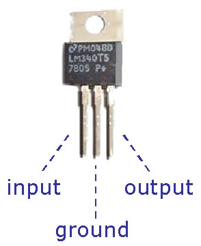
+5V Power Out -or- Regulated Power In (instead of PWR pin)7805 VOLTAGE REGULATOR
- Inputs 5V to 15V
- Outputs 5V
- Works best with >7V
- Heating up is normal
- Really hot = something wrong
- Costs only $1-$2

WIRING THE BX

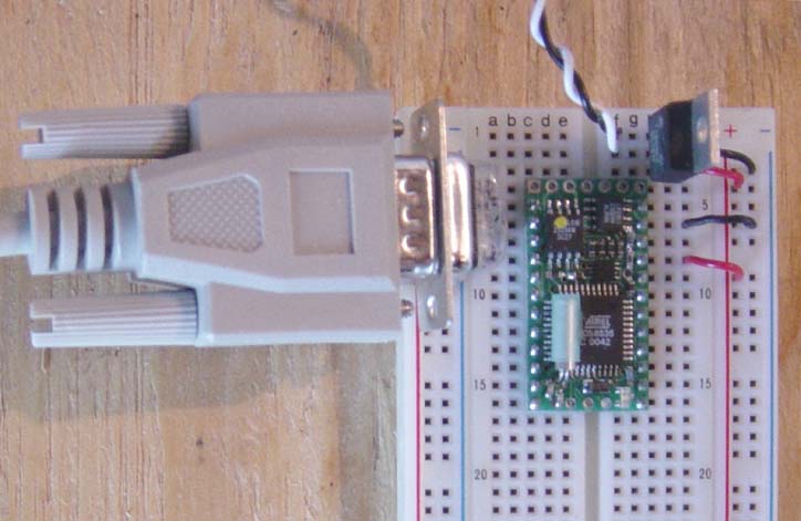
If using an external regulator, power the chip to pin 21 - the BX senses the input automatically. Using an external regulator is also very convenient for prototyping since your whole board can have a 5V power bus which most other IC’s (Integrated Circuits) expect.
Power can come from ordinary AC adaptor or batteries. One 9V battery is enough to power the BX-24 and a few other components.
Programming cable is a regular serial cable (DB9) with a simple custom-made adaptor (details in later section). It plugs into any available serial port on your computer.
As you can see, it is not necessary to connect the Reset pin, the Power pin, or the other Ground pin.