DESIGNING PHYSICAL INTERFACES:
interacting with our world
May 31 - June 9, 2004
instructors: eric forman & cynthia lawson
LECTURE 4: DIGITAL IN & OUT & ANALOG IN
INPUT
- Interactivity = Input <--> Output
- Sensing the physical world
- Types of input:
- Viewer / User
- Environment
Considerations of input and output are the key factors in designing an interactive project. Examples of input can range from a mouse click, a keyboard key pressed, or as sophisticated as an arm wave or slight eye movement. The objective of this course is to explore non-traditional input interfaces, like physical ones, to interact with screen-based computer graphics.
Therefore this section focuses on exploring the possibility of a physical interface as input. We will consider input that senses the user (such as touching, pressing, turning), a user in her/his environment (such as motion and proximity) and even a user’s environment (such as light and temperature).
Ultimately, for most successful uses of non-traditional inputs, it will be important to define a clear relationship between the input and output. Not only from a conceptual standpoint, but from a usability one, the user should understand how they are bringing about change, and how they can control it. If the input is sensed from the environment, and not affected at all by a person’s presence, this should also be clear.
SENSORS
- Digital vs. analog
- 0 or 1 vs. range from 0 to 255
- Common sensor types
- Pressure: FSR - force-sensitive resistor
- Temperature: thermistor
- Motion: flex sensor or potentiometer
- Distance: infrared or sonar
- Light: photocell
- Homemade sensors!!!
A sensor can be classified in many ways, including if it’s digital or analog. Digital inputs are basically binary switches - they are helpful to know the state of something - a person is either there or not, the light is either on or off, the ball was either picked up or not. Analog inputs allow the program to understand ranges of events: not only is the person there, but how close are they; not only is the light on, but how intense is it lit, etc.
Digital inputs are those that sense in binary mode. From the standpoint of the input device, this means it can detect on/off or 1/0. The device reading this input (e.g. the microcontroller) receives either a 1 or a 0, which in terms of the BX-24, means 5 Volts or 0 Volts. An example of digital input is a switch connected to power. The pin of the BX is previously grounded, so that when the switch is open, the pin reads 0 Volts, and the BX receives a 0. When the switch is closed, the pin reads 5 Volts, and the BX thus reads a 1.
Analog input senses a range of numbers, from 0 to 255 in the case of the BX. An analog sensor serves the role of a variable resistor, in that it’s causing the voltage at the input pin to fluctuate from 0 to 5 Volts. An example of analog input is a flexible sensor which values change according to how much the sensor is flexed. According to its flex, the sensor applies a higher or lower resistance to the pin from voltage, causing the voltage at the pin to change.
Key factors for determining which sensor to use are its intended use and application, its cost & availability, and its ease-of-use. It’s important to note that even if a sensor is intended to be used for analog input, some can be modified, either in hardware or software, to serve as digital switches. For example, a photocell can be used to determine intensity of light (analog), as well as to know if there is light or not (digital.)
Despite the enormous amount of sensors in the market, it is also quite feasible to find that the best solution to your problem is a homemade sensor (e.g. two pieces of metal touching as a switch).
USING SENSORS
Steps to consider:
- Sensor research
- Test w/o microcontroller - multimeter
- Test w/ microcontroller - debug.print
- Integrate into program & functionality
After determining what sensor best serves your application, the next key step is to understand how it works. Specifications such as input and output voltages, number of connections, and how to use them, are crucial in successfully using a sensor. After the specifications are understood, and the sensor is connected in its desirable way, it’s usually a good idea to test it without the microcontroller. You want to make sure the sensor is working on its own, before interfacing it with the BX-24, so as to troubleshoot with as few components as possible. Once the sensor works on its own, the next step is to integrate it with the microcontroller to make sure the BX-24 is reading the various values from its input pin. If the BX successfully receives the sensor’s information, the last step is to integrate these values into the larger program and functionality intended for the sensor.INPUT - DIGITAL SWITCH

The BX-24 works under digital logic. This is to say that in its lowest level of programming, the BX works with ones and zeros (i.e. binary.)
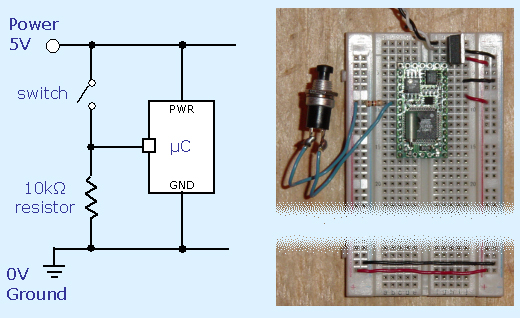
The picture shows a standard method of hooking up digital input. µC in the schematic is short for microcontroller (µ = micro). Note in the photo that power and ground are carried over to the left side buses - this is convenient standard practice.
When the switch is closed, current flows from the 5V to the pin. The connection from the input pin to ground is used to ensure the pin doesn’t read any stray voltage from the open switch. The 10k resistor bridging the pin to ground is necessary to prevent a short. Since current always takes the path of least resistance, the current flows from power directly to the pin, avoiding the path to ground (and therefore preventing a short circuit). When the switch is open, the pin is grounded, and the BX will read a 0 as the input value.
Digital input is read with the function getPin(pinNumber), which returns a 1 or a 0.
- Reading ADC values & responding to them
- getADC(pinNumber)
- Pin number must be 13-20
- Returns a value between 0-1023
INPUT - ANALOG SENSOR

With other microcontrollers, reading analog input requires implementing an analog-to-digital converter with external components and programming. The BX-24 has such a converter embedded already, making analog input very easy.
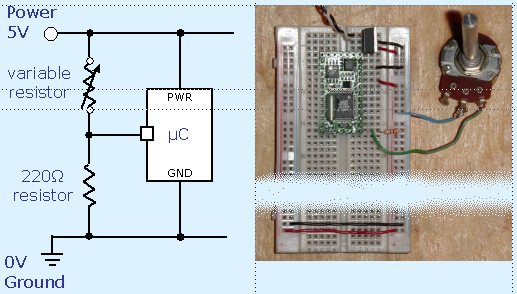
The example shown in the image is the wiring for a potentiometer, a common type of variable resistor. How the analog sensor is connected to the pin will depend in great part on the sensor’s specifications.
READING ANALOG SENSORS